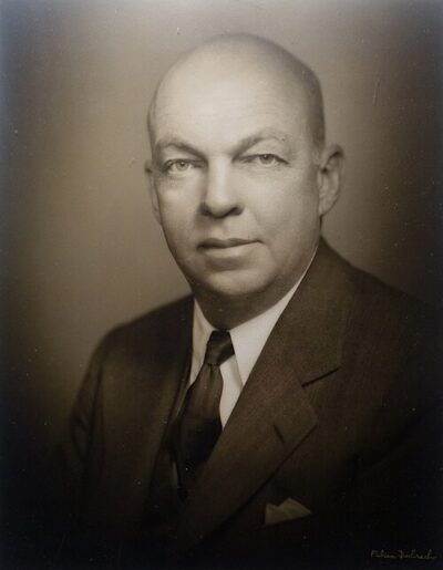
Armstrong oscillator
Armstrong oscillator is an electronic oscillator circuit which uses an inductor and capacitor to generate an oscillation.
All 3 facts, and where they come from
Facts
3 facts · 0 confirmed by two sources · 0 cited · 3 from one source
Where this comes from
Papalocal keeps its own record. It started from these sources; what each one said is kept here as it was copied, so a change on their side never changes this page by itself. Tap one to read its version.
What Wikidata says · copied November 17, 2026 · revision 2488794244
- Described as
- electronic oscillator circuit which uses an inductor and capacitor to generate an oscillation
- Other names
- Meissner oscillator, tickler oscillator
- What it is
- electronic oscillator
- Named after
- Edwin Howard Armstrong; Alexander Meissner
- Wikipedias with a page
- 15
Wikidata item Q283811 (wikidata.org/wiki/Q283811), public domain (CC0). Copied 2026-11-17.
What Wikipedia says · copied November 17, 2026 · revision 1362701487
The Armstrong oscillator (also known as the Meissner oscillator) is an electronic oscillator circuit which uses an inductor and capacitor to generate an oscillation. The Meissner patent from 1913 describes a device for generating electrical vibrations, a radio transmitter used for on–off keying. Edwin Armstrong presented in 1915 some recent developments in the Audion receiver. His circuits improved radio frequency reception. Meissner used a Lieben-Reisz-Strauss tube, Armstrong used a de Forest Audion tube. Both circuits are sometimes called a tickler oscillator because the distinguishing feature is that the feedback signal needed to produce oscillations is magnetically coupled into the tank inductor by a "tickler coil" (L2, right). Assuming the coupling is weak but sufficient to sustain oscillation, the oscillation frequency f is determined primarily by the LC circuit (tank circuit L1 and C in the figure on the right) and is approximately given by
f=12πLC
This circuit was widely used in the regenerative radio receiver, popular until the 1940s. In that application, the input radio frequency signal from the antenna is magnetically coupled into the LC circuit by an additional winding, and the feedback is reduced with adjustable gain control in the feedback loop, so the circuit is just short of oscillation. The result is a narrow-band radio-frequency filter and amplifier. The non-linear characteristic of the transistor or tube also demodulated the RF signal to produce the audio signal.
When the circuit is allowed to oscillate intermittently, it can become a superregenerative receiver.
The circuit diagram shown is a modern implementation, using a field-effect transistor as the amplifying element. Armstrong's original design used a triode vacuum tube.In the Meissner variant, the LC resonant circuit is exchanged with the feedback coil, i.e., in the output path (vacuum tube plate, field-effect transistor drain, or bipolar transistor collector) of the amplifier (e.g., Grebennikov, Fig. 2.8). Many publications, however, embrace both variants with either name. English speakers call it the "Armstrong oscillator", whereas German speakers call it the "Meißner oscillator".
From the Wikipedia article “Armstrong oscillator” (en.wikipedia.org/wiki/Armstrong_oscillator), by its contributors, under CC BY-SA 4.0 (creativecommons.org/licenses/by-sa/4.0/). Copied 2026-11-17; not changed.
Confirmed Two sources agree. Cited One source, and it names where it got it. One source One source, without a reference of its own. Sources disagree The sources disagree. We show the best-supported value and keep theirs below.